Introduction
The 6.9 and 7.3 liter V-8 Ford diesel produced by International Harvester, uses an Indirect Injection fuel system, which consists of several parts, most notably of which are the Stanadyne manufactured model DB-2 rotary fuel injection pump, the steel fuel lines leading from this pumps output head, and which are connected to eight individual fuel injectors, which together, regulate, control, and supply fuel for the combustion process inside the engine. During the life of the engine, these parts are in constant use, as the injection pump rotates as part of the valve train, and the injectors fire once per power stroke of each cylinder. These parts, generally speaking, are medium wear items, and typically last about 100,000 miles. The main factor determining the lifespan of these parts is the quality of the fuel being used in the vehicle, and any additives that are being used. Due to the high tolerances inside the injection pump, a supplemental lubricity fuel additive is always recommended for longest life. Since the engine is rated for 300,000 miles, this group of parts typically requires replacement several times over the lifespan of the engine. This article will attempt to guide individuals engaged in the pursuit of this activity.
Please refer to the below drawing for the following commentary.
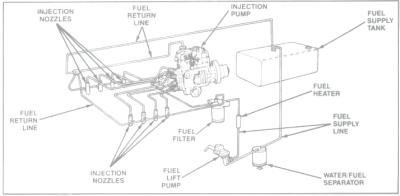
Aside from the problems associated with wear and the needed replacement of these components, it is also important to note that periodic inspection of the fuel injection nozzles is a wise investment of time, as poor performing injectors waste fuel and rob the engine of power. It is also possible for badly misbehaving injectors to introduce engine damaging knocks due to leaky pintle tips. Therefore, one of the more common service concerns not related to direct replacement of the main components is the condition of the injector to fuel return line connection. In the diagram above, please note the routing of the fuel return line which attaches to all eight injectors. The method of attachment and servicing procedures will be noted during the injector removal and replacement, but for the benefit of those reading this article specifically for that procedure, you may skip the section on injection pump replacement.
Component removal
In order to completely renew the fuel system, the fuel injection pump and injectors will be replaced simultaneously. The fuel injection lines are good for the life of the vehicle, provided that no harm comes to them, consequently this article will assume that the lines are being re-used. The fuel return lines will also be replaced along with the small parts associated therewith.
 Begin
by removing the air cleaner. The air
intake should be covered in some manner.
For this procedure I have used duct tape, which works fine provided that
the adhesive doesn’t stick too well to the intake screen. A layer of wax paper over the screen will
prevent this. Also, disconnect the
throttle cable/cruise control cable and bracket from the engine, and position it
out of the way. The throttle cable is
removed from the injection pump, by simply pulling the cable off the ball (pull
or pry towards the passenger side fender). If you are going to reinstall the
same injection pump for any reason, be sure to mark the relationship between
the pump and pump housing, to preserve the timing setting.
Begin
by removing the air cleaner. The air
intake should be covered in some manner.
For this procedure I have used duct tape, which works fine provided that
the adhesive doesn’t stick too well to the intake screen. A layer of wax paper over the screen will
prevent this. Also, disconnect the
throttle cable/cruise control cable and bracket from the engine, and position it
out of the way. The throttle cable is
removed from the injection pump, by simply pulling the cable off the ball (pull
or pry towards the passenger side fender). If you are going to reinstall the
same injection pump for any reason, be sure to mark the relationship between
the pump and pump housing, to preserve the timing setting.
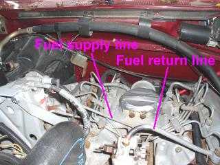
Next, remove the fuel supply line and the fuel return line. The fuel supply line will need to be unscrewed from both ends. On early 6.9 engines, the fuel line connects to the 90 degree adapter on the pump. Both the line and adapter must be removed separately. On 7.3L engines, the fuel supply line connects to the front of the pump directly. A small amount of fuel will leak out during these procedures. The return line at the top of the pump is rubber, and can simply be removed by unclamping the line at the pump, and pulling the hose off the barb.
 Next,
remove the injection pump gear access cover.
On early 6.9 engines, the cover is the oil fill tube. These engines typically do not have a tachometer
sensor installed. On all 7.3 and later
6.9 engines, the injection pump gear cover is a metal plate located on the
front of the injection pump gear housing, and in all cases, is held on by two
bolts. Remove the bolts, and remove the
plate. Note that silicon gasket material
is used to seal this part, and it will be necessary to clean off all the old gasket
material before reassembling.
Next,
remove the injection pump gear access cover.
On early 6.9 engines, the cover is the oil fill tube. These engines typically do not have a tachometer
sensor installed. On all 7.3 and later
6.9 engines, the injection pump gear cover is a metal plate located on the
front of the injection pump gear housing, and in all cases, is held on by two
bolts. Remove the bolts, and remove the
plate. Note that silicon gasket material
is used to seal this part, and it will be necessary to clean off all the old gasket
material before reassembling.
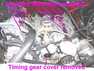
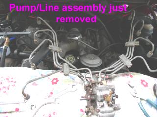
Proceed by removing the 5/16” bolts holding the timing gear to the injection pump. These bolts require a 16 point socket or open end wrench. The bolts are accessed through the hole exposed by removal of the cover in the previous step. Be careful not to misplace these bolts. Next, disconnect the 8 injection lines from the tops of the injector nozzles. Loosen the fittings fully, until each line can be lifted to expose the injector nozzle opening. Note that the #1 injector on 7.3L engines contains a pulse timing adapter attached to the injector. The line should be disconnected from the adapter, and then the adapter removed. Now remove the three 9/16” nuts and washers holding the injection pump to the injection pump gear housing. You may find it difficult to completely remove the nuts, without pulling the pump away from the pump gear housing. Once the nuts are loose or removed, pull the entire injection pump towards the rear of the engine. Disconnect the electrical connections from the pump, and complete the removal of the injection pump/injection line assembly from the engine.
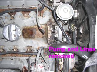
Now that the injection pump is removed, proceed with the removal of the fuel return lines. These are the rubber hoses still left on the injectors. The hoses connect to plastic caps which are press fitted over the injectors. Various configurations of these lines will be found on different 6.9 and 7.3 engines, depending on their year, the presence of a turbo, or modifications made by previous activities. The exact routing of the lines is not critical, and in fact, on the 1993 7.3 liter truck used for these photographs, I opted to change the line routing, and implemented a 6.9 style turbo equipped routing, even though this truck has no turbo. I did this in case I ever wanted to add one. Begin by disconnecting the returns at the rear of the engine, where they connect to the fuel return manifold on the driver’s side rear of the engine. The left bank and right bank will merge here in many cases, as will the line from the injection pump, if so equipped. Once the lines are disconnected from the manifold, pull up on the plastic caps covering each injection nozzle. These are seated by two rubber O-rings, and a small amount of pressure will pop them loose. Carry the line assemblies to your workbench, as well as the injection pump and line assembly.
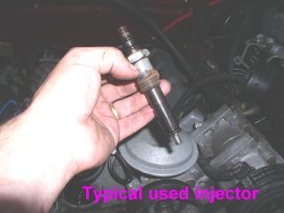
Next, remove the 8 injection nozzles. Use compressed air to clean the area around all the nozzles as you loosen them, to keep dirt and rust out of the injector bore. Each injector has a copper washer located near the nozzle tip. Make sure the washer comes out with the nozzle. Note any significant carbon build up on the injector body which may indicate a bad sealing of the injector. A ruff or irregular injector bore seat in the cylinder head may require cleaning which is beyond the scope of this article. Take the 8 injectors to your workbench, and cover the injector bores to prevent entry of dirt. If you have any intention of servicing your glow plugs, there will never be a better time, but that is beyond the scope of this article. I would recommend consulting with the resources of the 6.9 or 7.3 IDI forums on “TheDieselStop.com” for this task.
Injector evaluation, and replacement
Most people reading this article
will not have the test equipment used in the pictures below. However, it is important to test ALL injectors, new or used. If you do not have the ability to do these
tests yourself, seek out a qualified injection service facility to have your
injectors tested. Most will test for
free, or a nominal fee. Replacing one
untested injector for another, only yields exchanging one unknown for another,
and may introduce problems later. The
following pictures outline the general condition you may find your injectors
in. In this example case, the tests
yield results which indicate 50% of the injectors in this subject truck are
bad.
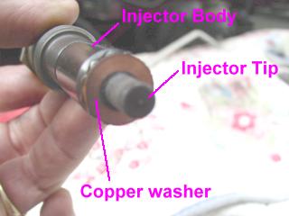
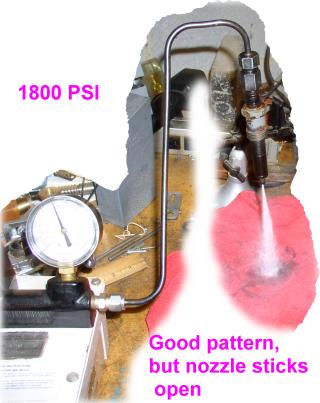
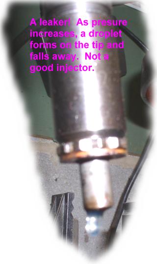
In the above pictures, you see two
different injectors and their failure modes.
Injectors are tested by an injection nozzle tester, in this case a
Rotunda unit. A simple device, it has a
hand operated lever, which like a bottle jack handle, operates a pressure
producing piston. Calibration fluid from
the tank is pumped by hand into the injection nozzle. The attached gauge allows the pressure build
up to be read. 1800 PSI is nominal for
these injectors. Some make it to that
value, others open short of it. As
pressure builds, tips may leak, or the injector may open prematurely.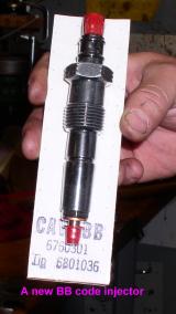
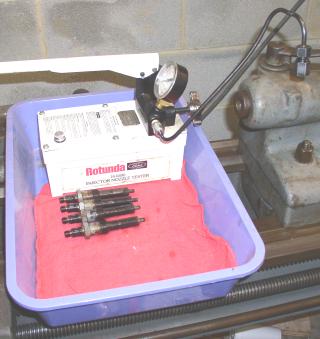 The complete nozzle testing rig and 4 good injectors is shown at left. I opted to replace all 8 injectors with newly
rebuilt Lucas units. The truck was
originally equipped with E code injectors.
I replaced them with BB Code injectors.
There is still much debate as to what the significance of the letter
codes are. The coding is determined by
components used in the nozzle end of the injector, and injectors can be found
stamped with the letters A, B, D, E, AA, BB, G and perhaps others. What every one does agree on however, is that
it is important not to mix letter codes. Make sure all 8 of your injectors are the
same. The letter code is stamped on the
nut portion of the injector, where you used the wrench to remove it.
The complete nozzle testing rig and 4 good injectors is shown at left. I opted to replace all 8 injectors with newly
rebuilt Lucas units. The truck was
originally equipped with E code injectors.
I replaced them with BB Code injectors.
There is still much debate as to what the significance of the letter
codes are. The coding is determined by
components used in the nozzle end of the injector, and injectors can be found
stamped with the letters A, B, D, E, AA, BB, G and perhaps others. What every one does agree on however, is that
it is important not to mix letter codes. Make sure all 8 of your injectors are the
same. The letter code is stamped on the
nut portion of the injector, where you used the wrench to remove it.
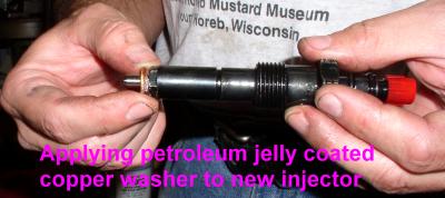
 Once
you have decided on the injectors you’re going to install, be sure to use new
copper washers, and use petroleum jelly to hold them onto the end of the
injector. If you have protective caps on
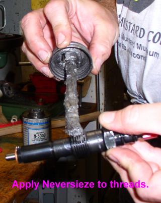
your injectors, remove the injector tip cap, but retain the top cap for now. Apply a graphite based anti seize compound to
the injector threads and carefully thread the injectors into the injector
bores. Tighten the injectors to 33 foot
pounds.
Once
you have decided on the injectors you’re going to install, be sure to use new
copper washers, and use petroleum jelly to hold them onto the end of the
injector. If you have protective caps on
your injectors, remove the injector tip cap, but retain the top cap for now. Apply a graphite based anti seize compound to
the injector threads and carefully thread the injectors into the injector
bores. Tighten the injectors to 33 foot
pounds.
This completes the injector portion of the work.
Return line refit
Obtain new injector caps, hoses and clamps. These may be in the form of individual parts purchased at a Ford or IH dealer, or an injector servicing kit, such as those sold by DIS, DPS-Performance, MWFI and other online sources. If re-using existing injectors, replace all the O-rings that were on them. Keep in mind that the caps sold for use on 6.9 and 7.3 engines are different, in that the two engines used different size hose, and consequently different size nipples on the caps. It is possible to use either size on either engine, however for the purposes of this article, it is advisable to replace like kind for like kind, and keep the routing of the hoses the same. In most cases the hose is not pre-cut to length, and comes in a spool. You will need to cut the hose to the right length to install it. Use the old hoses as a guide to cutting them to the right length. Begin by removing the red injector caps that came on the new injectors as shown in the above photos. If reusing old injectors, you most likely do not have these. Apply some petroleum jelly to the O rings, and press the new fuel return line caps onto the injectors. The caps will seat with a good “click”. You will know they are on properly when you see that the top of the cap is seated on the shoulder of the injector, below the injection line connection threads. Under no circumstance should you find that the nut on the injection line is pushing down on the cap when you go to install the injection lines. Orient the caps in such a way that the cap barbs point towards each other. Once all the caps are on, take each length of new hose that you have prepared, and place a clamp on the hose an inch or two from the ends. Push the hose onto the return line cap barbs, and slide the clamp towards the end of the hose, seating it on the hose close to the end for maximum grip. The hoses between injectors should be straight and not bowed. If they are bowed, they are either too long, or not on the return line cap barbs fully. If the hose is too short, it will not cover enough of the barb to seal reliably. Ideally, the end of each hose length should all but touch the return line cap body. Once all the lines are installed, review the routing. Be sure that the fuel filter head and injection pump both have returns and that all returns can make it back to the fuel tank. A common mistake may be to not connect the passenger side bank with the drivers side bank in some fashion. Review all hose connections to make sure the spring clamps are properly seated, and ensure that no return line caps have come off of their injectors. You are now ready to install the injection pump and lines. If you still have the red caps to cover the injector threads, go ahead and put them back on. This will keep dirt out of the injectors.
Injection pump replacement
The injection pump you have removed from the truck is full of fuel. If you are going to return it as a core for an exchange, it is best to drain it. There are two ways to accomplish this. The first is to remove the triangular plate from the passenger side lower portion of the pump body. This is the same plate used to access the fuel screw. Another way is to remove the top cover. If you are unsure of the condition of your injection pump, and the truck was running OK with it, you may wish to examine the pump to look for signs of the timing advance ring deteriorating. You must remove the top cover to do this. If you’re using a new or freshly rebuilt pump, do not attempt to remove any covers, or you may void the warranty. If your sending your old pump away, and do not have the new pump available, be sure to remove the return line fitting elbow or barb, and the fuel inlet adapter. It is better for you to have to have too many of these parts in the event the new pump comes with them, then for you to have to find replacements once the new pump has arrived.
WARNING! Before proceeding read this important note!
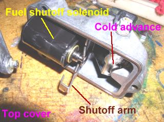
Remove the top cover
at your own risk. If you remove it, and
do not reinstall it properly, your engine could enter a runaway state upon
restarting. Pay particular attention to
the way the fuel shut off arm must fit in the pump body, and ensure that you
can hear a good click when you apply power to the pump BEFORE you attempt to
start the truck. If the pump is not
assembled correctly, full throttle would be applied and disconnecting power
from the pump would not stop it. Only
the removal of fuel or air would.
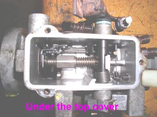 To
remove the top cover, remove the three bolts holding it on, and lift it off,
sliding it towards the flange end of the pump.
At this point you will be looking at a pool of fuel oil, assuming it
hasn’t leaked out somehow. Devise a way
to dump the contents into a filter media so you can look for bits of black
plastic. If some are found, then you
definitely do not want to reuse this pump.
To
remove the top cover, remove the three bolts holding it on, and lift it off,
sliding it towards the flange end of the pump.
At this point you will be looking at a pool of fuel oil, assuming it
hasn’t leaked out somehow. Devise a way
to dump the contents into a filter media so you can look for bits of black
plastic. If some are found, then you
definitely do not want to reuse this pump.
Remove all of the fuel injection lines from the pump as a single unit. It will actually break down into left and right banks as you remove them, provided that you do not remove the line clamps (the 3 or 4 bands that hold the lines together at various points between the pump and nozzle connectors). I find it convenient to have both the old and new pumps next to each other, to ensure that I transfer the lines to the correct connectors. When tightening the lines on the new pump, pay particular attention to the lines that are at the bottom of the round pump head. They are the most difficult to access when the pump is on the engine, and you don’t want to have these leaking when the pump is installed. The other lines can all be tightened once the pump is on. Be sure to hold the pump-side fittings with a wrench as you tighten the lines.
If you’re installing a new injection pump, check for the red
plugs that cover fitting attachment points.
You will need to remove these plastic plugs and transfer the plumbing parts
from the old pump to the new one. Usually the return line fitting will need to
be transferred to the new pump, as may the fuel inlet reducer. Once all the lines and fittings have been
transferred to the new pump, prepare the truck and pump for installation. The gear driven 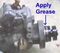 end
of the injection pump has a rubber O-ring on the pump body. Lubricate
end
of the injection pump has a rubber O-ring on the pump body. Lubricate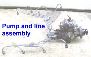 this O-ring with petroleum jelly. Verify
that the valley pan on the engine is clean and clear of loose parts and tools,
and ensure that the throttle cable is still out of the way, and that the intake
is covered. Lower the injection pump and
lines as a unit into the engine bay, and start the gear driven end of the injection
pump, into the gear housing. As you
lower the lines and slide the pump into the gear housing, take note that the
alignment dowel on the injection pump gear is going to engage the slot in the
injection pump gear mounting flange. It
may be necessary to partially remove the pump and turn the pump shaft by hand
to achieve the needed alignment. Once
you have the pump fully seated, be sure to put the 9/16” washers and nuts on
the pump mounting studs. It may be
necessary to move the pump slightly rearward to get the needed clearance to
start the nuts. Align the timing marks
(factory scribed lines if new pump, or the marks you made if the old pump is
going back on) and tighten the three 9/16” nuts. Install the 3 bolts into the injection pump
gear and thread them into the injection pump gear flange. Tighten to 7 ft-lbs. Apply fresh silicon sealer to the oil
filler/gear cover and install. Tighten
the 2 bolts which hold it on. Reconnect
the injection pump return line hose. Reinstall
the fuel supply line between the front of the pump, and the filter head. For pumps equipped with the 90 degree adapter
style fitting, it is important to get the adapter tight, and still be pointed
in the right direction. This is one
instance where the 7.3 style line has a clear advantage over the 6.9. Now, remove the injector thread caps (those
red plastic ones if you had them on there) and place a rag between the injector
and the injector line above it. You are
now ready to prime the engine. Remove
the air intake cover, and ensure that no debris will be sucked into the
intake. Because you may need to crank
the engine a bit to prime the new injection pump, it is advisable to manually
control the electrical circuits for cranking and pump activation, rather then
using the ignition key. This is because
you should avoid actuation of the glow plugs in order to save them and your
battery. If your truck is equipped with
a manual glow-plug push button as some have done, then this precaution is not
necessary. Apply 12 volts positive to
the forward most electrical connection on the injection pump. This can be done with a jumper wire from the
nearest battery positive post. A wire
with an alligator clip at each end works best for this task. You should hear a distinct click when you
connect the wire. Ensure that the truck
is in neutral, and cannot move. Activate
the starter by connecting 12 volts positive to the starter solenoid on the
passenger side fender. The correct terminal to apply this voltage to will be the smaller top
forward connection. Simply pull
the normal lead off the post to expose it.
Note that you should not crank the engine for more than 10 seconds at a
time, and let it rest a good while between cranks to let the starter cool
down. Verify while cranking that you
have fuel at the filter head shrader valve.
Move the throttle lever on the injection pump to the full throttle
position. This will be towards the air
intake. Crank the engine in cycles, as
often as needed until the rags under the fuel injection lines get wet with
fuel. Once this happens, remove
electrical power from the injection pump, and verify that no fuel comes out
when cranking. This is the best way to
avoid a runaway situation that could result from improper installation of the
injection pump top cover. Connect the
fuel injection lines to the injection nozzles and tighten to 22 ft-lbs. Connect the throttle cable and attach the
mounting bracket. Verify the operation
of the throttle cable, and movement of the injection pump arm. Ensure that the spring returns the pump to
idle. Reconnect all normal electrical
connections, and proceed to start the truck normally. NOTE: If
you have difficulty getting the truck to start, slightly loosen half of the
injector lines at the nozzles. You may
hear a little hiss of air as the line is loosened, indicating trapped air in
the injection lines. You may need to
tighten and loosen these lines multiple times to force the air out. It is important not to make them too loose,
or air may get back in. Keep the pump at
full throttle until the engine starts to catch. Once it fires, it will run
very rough. Shut it off and reinstall
the air cleaner, and double check the tightness of all injector lines, at both
the pump and injector ends. Restart and
check for fuel leaks. Once a smooth idle
is obtained, verify that the cold idle
solenoid is operating by letting the engine reach about 130 degrees water
temperature, on high idle, at which time the high idle solenoid should drop
off. Normal engine idle speed is 650
RPM, and the timing should be set to 8.5 degrees at 2000 RPM using the pulse
timing method. This is valid for 6.9 and
7.3 engines. Over the course of the next
3 driving cycles, the truck may start with a rough idle and then smooth
out. The rough start should disappear
after all air has purged itself from the system. Continue to check for leaks through the next
several hours of operation. If you
encounter hard starts after the truck has been sitting overnight, it is very
likely that one of the return lines is not sealing properly. Check for leaks and examine all connections
for tightness.
this O-ring with petroleum jelly. Verify
that the valley pan on the engine is clean and clear of loose parts and tools,
and ensure that the throttle cable is still out of the way, and that the intake
is covered. Lower the injection pump and
lines as a unit into the engine bay, and start the gear driven end of the injection
pump, into the gear housing. As you
lower the lines and slide the pump into the gear housing, take note that the
alignment dowel on the injection pump gear is going to engage the slot in the
injection pump gear mounting flange. It
may be necessary to partially remove the pump and turn the pump shaft by hand
to achieve the needed alignment. Once
you have the pump fully seated, be sure to put the 9/16” washers and nuts on
the pump mounting studs. It may be
necessary to move the pump slightly rearward to get the needed clearance to
start the nuts. Align the timing marks
(factory scribed lines if new pump, or the marks you made if the old pump is
going back on) and tighten the three 9/16” nuts. Install the 3 bolts into the injection pump
gear and thread them into the injection pump gear flange. Tighten to 7 ft-lbs. Apply fresh silicon sealer to the oil
filler/gear cover and install. Tighten
the 2 bolts which hold it on. Reconnect
the injection pump return line hose. Reinstall
the fuel supply line between the front of the pump, and the filter head. For pumps equipped with the 90 degree adapter
style fitting, it is important to get the adapter tight, and still be pointed
in the right direction. This is one
instance where the 7.3 style line has a clear advantage over the 6.9. Now, remove the injector thread caps (those
red plastic ones if you had them on there) and place a rag between the injector
and the injector line above it. You are
now ready to prime the engine. Remove
the air intake cover, and ensure that no debris will be sucked into the
intake. Because you may need to crank
the engine a bit to prime the new injection pump, it is advisable to manually
control the electrical circuits for cranking and pump activation, rather then
using the ignition key. This is because
you should avoid actuation of the glow plugs in order to save them and your
battery. If your truck is equipped with
a manual glow-plug push button as some have done, then this precaution is not
necessary. Apply 12 volts positive to
the forward most electrical connection on the injection pump. This can be done with a jumper wire from the
nearest battery positive post. A wire
with an alligator clip at each end works best for this task. You should hear a distinct click when you
connect the wire. Ensure that the truck
is in neutral, and cannot move. Activate
the starter by connecting 12 volts positive to the starter solenoid on the
passenger side fender. The correct terminal to apply this voltage to will be the smaller top
forward connection. Simply pull
the normal lead off the post to expose it.
Note that you should not crank the engine for more than 10 seconds at a
time, and let it rest a good while between cranks to let the starter cool
down. Verify while cranking that you
have fuel at the filter head shrader valve.
Move the throttle lever on the injection pump to the full throttle
position. This will be towards the air
intake. Crank the engine in cycles, as
often as needed until the rags under the fuel injection lines get wet with
fuel. Once this happens, remove
electrical power from the injection pump, and verify that no fuel comes out
when cranking. This is the best way to
avoid a runaway situation that could result from improper installation of the
injection pump top cover. Connect the
fuel injection lines to the injection nozzles and tighten to 22 ft-lbs. Connect the throttle cable and attach the
mounting bracket. Verify the operation
of the throttle cable, and movement of the injection pump arm. Ensure that the spring returns the pump to
idle. Reconnect all normal electrical
connections, and proceed to start the truck normally. NOTE: If
you have difficulty getting the truck to start, slightly loosen half of the
injector lines at the nozzles. You may
hear a little hiss of air as the line is loosened, indicating trapped air in
the injection lines. You may need to
tighten and loosen these lines multiple times to force the air out. It is important not to make them too loose,
or air may get back in. Keep the pump at
full throttle until the engine starts to catch. Once it fires, it will run
very rough. Shut it off and reinstall
the air cleaner, and double check the tightness of all injector lines, at both
the pump and injector ends. Restart and
check for fuel leaks. Once a smooth idle
is obtained, verify that the cold idle
solenoid is operating by letting the engine reach about 130 degrees water
temperature, on high idle, at which time the high idle solenoid should drop
off. Normal engine idle speed is 650
RPM, and the timing should be set to 8.5 degrees at 2000 RPM using the pulse
timing method. This is valid for 6.9 and
7.3 engines. Over the course of the next
3 driving cycles, the truck may start with a rough idle and then smooth
out. The rough start should disappear
after all air has purged itself from the system. Continue to check for leaks through the next
several hours of operation. If you
encounter hard starts after the truck has been sitting overnight, it is very
likely that one of the return lines is not sealing properly. Check for leaks and examine all connections
for tightness.
In closing, a final comment, with regard to pump timing. A properly timed pump can make the difference between a great truck which the owner loves to drive and wants to keep, and a truck that the owner feels he may have wasted his money on. In almost all cases, when the injection pump mark is aligned with the mark provided on the pump gear housing (known as being “static timed”), the pump will be retarded several degrees. The result is a smooth running engine, with very clear exhaust and the owner may find the performance to be satisfactory. However, until the pump is advanced to 8.5 degrees (factory spec) BTDC using the pulse method, the true performance of the engine will not be realized. A properly timed engine (which has been dynamically timed with special equipment) will have significantly more pick up, and much better fuel economy that one that is static timed. It will also smoke a bit more! Therefore, in order to get the most out of your new fuel system, it is highly recommended that you seek out a qualified shop to perform dynamic timing on your truck. Use caution! Many shops “time by ear” and do not have the actual equipment. I consider myself to do very well timing by ear, but I have found that I can be as much as 2 degrees off. Factory spec allows for 1 degree of deviation. Get a shop that has a good and valid timing meter for the job! You really can’t substitute the functionality of a good quality tool.
Mel Agne has authored over 10,000 posts on Thedieselstop.com
and wrote the
definitive article on servicing head gaskets and installing a turbo charger on
the 6.9 engine. He has also conducted
numerous timing clinics at IDI related events.