
By Rob Fox
In the never ending quest of lowering EGTs, I started looking at the different WM kits on the market. The more I researched, the more I liked the idea. I found several good looking kits, but for what comes in the kits the prices seemed rather high. In many of the kits, it appeared that much of the expense was tied up in an EGT trigger mechanism that I wouldn’t use. My belief is (and was at the time) that I know my truck, and I also know the kind of hill and load that will cause me to outrun my comfortable EGT limit of 1100°. So my thinking was, “I only want to use this system when I have it manually armed, and when my boost reaches a certain pressure.” I figured I only wanted to use it for short bursts, and I just didn’t like the idea of an EGT trigger cycling it on and off while I was trying to do my thing. So I spent a lot of time on trial and error and eventually came up with what I call the Splash system.
My single biggest use for the system is when I’m hauling the camper up a hill and I come to a slower moving truck in the right lane. Instead of hanging behind him for fear of “running out” of EGTs while trying to pass and ending up impeding traffic, I just turn to the Splash system.
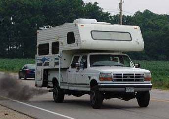
I flick the switch, grab a gear, and mash the throttle. Out into the left lane I go with about 30 extra hp (total seat of the pants guesstimate), 2.5 extra lbs of boost, and EGTs holding strong between 950° - 1000°. After passing my fellow RVer with ease, I pop her back into 5th, settle back into the right lane, and hit resume on the cruise like nothing ever happened.
The only other practical use for water injection in my opinion is ¼ mile runs. It’s a fairly cheap way to gain a few extra ponies, and with enough methanol in the mix, you could probably shave some time off your run. For anything else, I don’t think you can haul along enough water. My single stage system flows about 0.17 GPM. So if you’re trying to climb that hour long grade 10mph faster by adding water injection, you’re going to need 10 gallons just for that one hill you’re thinking of. My advice is think short bursts and the system will do you well.
DISCLAIMER ************READ
THIS!*****************
By adding water injection, you are risking damaging your engine. Do not perform this mod if you are not willing to accept this fact. When a system is perfectly tuned to suit your engine, I personally believe there is little risk for engine damage. But you could be cruising along with water misting away and unbeknownst to you the system fails in some way that changes your beautiful fine mist to a straight liquid trickle. Liquid water in a diesel engine? Bad, bad news. I have read about more than a few catastrophic diesel engine failures whose owners believe water injection was the cause. At least one of which was based on the very system I’m about to describe. The bottom line is when dialing in one of these systems take no short cuts.
w Bench test, bench test, bench test!
w Put your system together on the bench first.
w Measure the pressure your pump is putting out.
w Get out your stop watch and run your mist into a jug for 5 minutes. How much water did you capture in the jug? Do the numbers add up to the amount you thought you should be flowing?
w Is there water seeping out in big drops between the nozzle and the mounting bushing?
w And above all else, when finally testing your system on a running engine, your ear is the best troubleshooting tool you have. You know what your motor should sound like. When the water kicks on, it shouldn’t sound any different. No extra clatter, no new knocks, and no detonation. If you get any of these things, go back to the bench and find out what’s wrong.
*****************PROCEED
AT YOUR OWN RISK!*********************
System description:
Basically it’s a single stage system that comes on when the turbo reaches 7psi of boost.
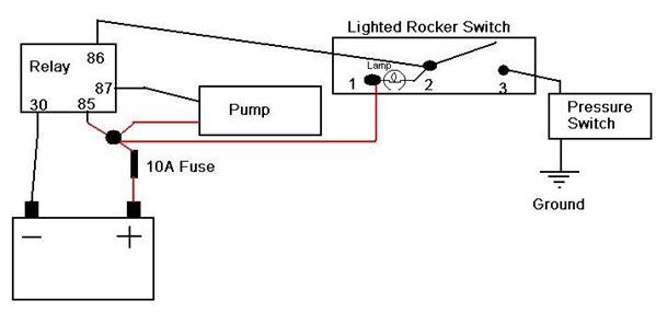
I have a lighted rocker switch in the cab that arms the system. With the system armed a pressure switch monitors the turbo boost, when it reaches 7psi the pressure switch activates a relay that turns on the pump and the light in the rocker switch. The light lets me know that the pump is on and the system is flowing water. The pump then delivers windshield washer fluid at 100psi to a nozzle that mists the fluid into the intake hat. The nozzle that I’m currently using limits the flow to approx .17 (point one seven) gallons per minute.
Now the fun begins, as soon as (and I mean AS SOON AS) the water starts flowing the boost jumps to 12.5 PSI and the EGTs pretty much level off. I haven’t been able to get above 950° F with an unloaded truck and the system on. You feel a slight seat of the pants power increase, but nothing like a 200 hp shot of nitrous or anything.
Also my waste gate is set to limit boost to 10psi when I’m not running water, but it gets pushed to 12.5 with the water on.
Wet part of the system:
I tried to start at the intake hat, and work my way back to the tank. All threads are wrapped with Teflon tape. A full parts list is included at the end of the article.
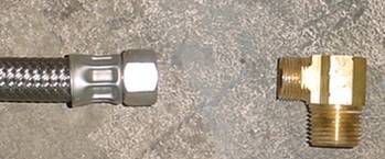
Here is a somewhat “exploded view” of the nozzle and various fittings.
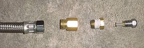 The
two pieces on the right (nozzle and bushing) are installed inside the intake
hat. About half of the bushing threads
will be exposed on the outside of the hat.
This allows you to screw on the 3/8th male compression to 1/4th FIP adaptor. The stainless steel line can then be
attached.
The
two pieces on the right (nozzle and bushing) are installed inside the intake
hat. About half of the bushing threads
will be exposed on the outside of the hat.
This allows you to screw on the 3/8th male compression to 1/4th FIP adaptor. The stainless steel line can then be
attached.
Here is the stainless high
pressure line going from the intake hat to the pump.
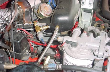 Also
note the T connection where I’ve hooked up my pressure switch. This allowed me to keep the boost gauge
connected. The pressure switch is just an
oil sending unit from a 1992 ford F350 with the 7.3L diesel engine. I knew that switch was good for something.
Also
note the T connection where I’ve hooked up my pressure switch. This allowed me to keep the boost gauge
connected. The pressure switch is just an
oil sending unit from a 1992 ford F350 with the 7.3L diesel engine. I knew that switch was good for something.
Here is the other end of the
stainless line where it attaches to the pump. .
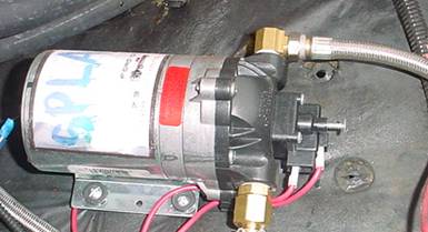 The
pump is mounted to the wheel well cover behind the passenger side battery
The
pump is mounted to the wheel well cover behind the passenger side battery
This is the adaptor needed
to attach the line to the pump.
Also, in the pump picture above, you can see a 3/8th
barb to 3/8th MIP fitting installed in the pickup side of the
pump. This allows you to attach your 3/8th
ID hose which will hookup to the tank.
This is the current makeshift
tank I’m using.
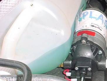 You
guessed it! It’s the actual jug that the
windshield washer fluid came in. I plan
to mount a 5 gallon tank under the bed some place eventually, but until then, a
gallon at a time seems to work just fine.
You
guessed it! It’s the actual jug that the
windshield washer fluid came in. I plan
to mount a 5 gallon tank under the bed some place eventually, but until then, a
gallon at a time seems to work just fine.
Electrical part of the system:
As for wiring it all up, it’s pretty simple. The main thing is to keep your wires long enough so you can route them neatly.
Parts list:
Mechanical:
(1) Nozzle at the flow rate of your choice.
I’m
using part number 3178K76 at http://www.mcmaster.com/
(1) 1/4th MIP to 1/8th FIP bushing
This
threads into a tapped hole (created by you) in the intake hat on the 1/4th
side, enough threads will be exposed on the outside of the hat. The nozzle also threads into this bushing on
the 1/8th side.
Pink
bag A-738 @ Home Depot
(1) 3/8th male compression to 1/4th FIP fitting
This
connects the stainless steel line to the bushing in the hat.
Green
bag A-116 @ Home Depot
(1)
The
elbow connects to the pressure side of the pump, and the stainless steel line
connects to the compression thread side of the elbow. Home Depot
(1) Shurflo 12 Volt 1 GPM On-Demand Diaphragm Pump
Old Model# 8000-541-236 new Model# 8009-541-236
This
pump is pressure adjustable and will maintain 100-120 PSI up to .3 GPM. www.northerntool.com
(1) 3/8th barb to 3/8th MIP fitting
This installs into the pickup side of the pump head. Home
Depot
Length of 3/8th ID hose
Need
enough to plumb from tank to pump. The
hose should be made of material that will standup to methanol
(4) Small hose clamps
Clamp
hose to pickup tube, and hose to pump.
Length of 3/8th metal pipe
This
is used for the pickup tube for the tank, should be 1-2 inches longer than the
tank is tall. I am currently using a
section of stainless steel brake line.
(1) Tank
I’m currently using a 1 gallon windshield washer fluid
bottle
(1) Roll of Teflon tape for all threaded connections.
.
Electrical:
(1) Heavy duty relay
DF005 From AutoZone
(1) Oil pressure sending unit
Niehoff OP80941 (owe P8 zero 941) Autozone
(1) Lighted rocker switch
Autozone
20 feet of 16ga wire
(7) Female spade type electrical connectors
(1) Round female barrel type electrical connector
(1) Round type electrical connector flat with hole in center
(1) Fuse holder with 10A fuse